Заглавная страница Избранные статьи Случайная статья Познавательные статьи Новые добавления Обратная связь FAQ Написать работу КАТЕГОРИИ: ТОП 10 на сайте Приготовление дезинфицирующих растворов различной концентрацииТехника нижней прямой подачи мяча. Франко-прусская война (причины и последствия) Организация работы процедурного кабинета Смысловое и механическое запоминание, их место и роль в усвоении знаний Коммуникативные барьеры и пути их преодоления Обработка изделий медицинского назначения многократного применения Образцы текста публицистического стиля Четыре типа изменения баланса Задачи с ответами для Всероссийской олимпиады по праву 
Мы поможем в написании ваших работ! ЗНАЕТЕ ЛИ ВЫ?
Влияние общества на человека
Приготовление дезинфицирующих растворов различной концентрации Практические работы по географии для 6 класса Организация работы процедурного кабинета Изменения в неживой природе осенью Уборка процедурного кабинета Сольфеджио. Все правила по сольфеджио Балочные системы. Определение реакций опор и моментов защемления |
Starter Motor Brush Length Standard: 12 mm (0.47 in.)Содержание книги
Поиск на нашем сайте Service Limit: 6.0 mm (0.24 in.)
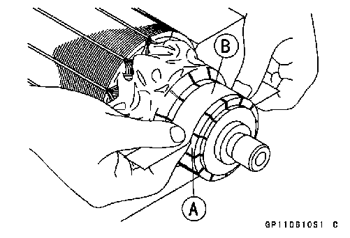
• Smooth the commutator surface [A] if necessary with fine emery cloth [B], and clean out the grooves.
replace the starter motor with a new one. Commutator Diameter Standard: 28 mm (1.10 in.) Service Limit: 27 mm (1.06 in.)
• Using the × 1 Ω hand tester range, measure the resis- tance between any two commutator segments [A]. Special Tool - Hand Tester: 57001-1394
• Using the highest hand tester range, measure the resis- tance between the segments and the shaft [B].
NOTE ○Even if the foregoing checks show the armature to be good, it may be defective in some manner not readily detectable with the hand tester. If all other starter motor and starter motor circuit components check good, but the starter motor still does not turn over or only turns over weakly, replace the starter motor with a new one.
• Using the × 1 Ω hand tester range, measure the resis- tance as shown. Terminal Bolt and Positive Brushes [A] Brush Plate and Negative Brushes [B] Special Tool - Hand Tester: 57001-1394
• Using the highest hand tester range, measure the resis- tance as shown. Terminal Bolt and Brush Plate [A] Terminal Bolt and Negative Brush Holders [B] Terminal Bolt and Yoke [C] Special Tool - Hand Tester: 57001-1394
• Remove: Bolt [A] and Cover [B]
• Disconnect the starter motor cable [B] and battery positive
(+) cable [C] from the starter relay [D].
Special Tool - Hand Tester: 57001-1394
Testing Relay Tester Range: × 1 Ω range Criteria: When battery is connected → 0 Ω When battery is disconnected → ∞ Ω
Electric Starter Circuit
1. Ignition Switch 2. Water-proof Joint B 3. Starter Lockout Switch 4. Ignition Fuse 10 A 5. Fuse Box 6. Starter Circuit Relay 7. Relay Box 8. Starter Motor 9. Starter Relay 10. Main Fuse 30 A 11. Battery 12 V 10 Ah 12. Sidestand Switch 13. Frame Ground 14. Joint Connector 15. Neutral Switch 16. Water-proof Joint C 17. Starter Button 18. Engine Stop Switch
This motorcycle adopt the daylight system and have a headlight relay in the relay box. The headlight does not go on when the ignition switch and the engine stop switch are first turned on. The headlight comes on after the starter button is released and stays on until the ignition switch is turned off. The headlight will go out momentarily whenever the starter button is pressed and come back on when the button is released. Headlight Beam Horizontal Adjustment • Refer to the Headlight Aiming Inspection in the Periodic Maintenance chapter. Headlight Beam Vertical Adjustment • Refer to the Headlight Aiming Inspection in the Periodic Maintenance chapter.
• Remove: Upper Inner Fairing (see Upper Inner Fairing Removal in the Frame chapter) Headlight Connector [A] Headlight Bulb Dust Cover [B]
Headlight Bulb [B]
NOTE ○Clean off any contamination that inadvertently gets on the bulb with alcohol or soap and water solution.
• Fit the projection [A] of the bulb in the hollow [B] of the headlight. • Install the hook [C].
• Fit the dust cover [A] onto the bulb [B] firmly as shown. Good [C]
• After installation, adjust the headlight aim (see Headlight Aiming Inspection in the Periodic Maintenance chapter).
• Remove the meter cover (see Meter Unit Removal/Instal- lation). • Disconnect the connector [A]. • Pull out the socket [B] together with the bulb.
 • Pull the bulb [A] out of the socket. • Pull the bulb [A] out of the socket.
• Replace the bulb with a new one.
• Remove: Upper Fairing (see Upper Fairing Removal in the Frame chapter) Mounting Bolts [A] • Installation is the reverse of removal.
• Remove: Seat Covers (see Seat Cover Removal in the Frame chapter) • Disconnect the connector [A]. • Unscrew the mounting bolts [B]. • Remove the tail/brake light [C].
Tail/Brake Light Installation • Installation is the reverse of removal.
• Remove: Screws [A] License Plate Light Cover [B] • Push and turn the bulb counterclockwise and remove it.
turn the bulb clockwise. ○Turn the bulb about 15°. • Install the license plate light cover. • Tighten: Torque - License Plate Light Cover Screws: 0.90 N·m (0.090 kgf·m, 8 in·lb)
1. Ignition Switch 2. Water-proof Joint A 3. Water-proof Joint B 4. Position Light 5. Headlight (High Beam) 6. Headlight (Low Beam) 7. Dimmer Switch 8. Passing Switch 9. Headlight Relay 10. Relay Box 11. Starter Relay Turn Signal Light Bulb Replacement • Unscrew the screw [A] and remove the lens [B]. ○Turn the lens counterclockwise. 12. Main Fuse 30 A 13. Battery 12 V 10 Ah 14. Frame Ground 15. Tail/Brake Light 16. License Plate Light 12 V 5 W 17. Joint Connector 18. Water-proof Joint C 19. Regulator/Rectifier 20. Fuse Box 21. Headlight Fuse 10 A 22.
turn the bulb clockwise. ○Turn the bulb about 15°. • Install the projections of the lens to the dints of the turn signal light.
• Remove: Left Upper Inner Fairing (see Upper Inner Fairing Re- moval in the Frame chapter) Turn Signal Relay [A]
flash for one minute. Turn Signal Relay [A] Turn Signal Lights [B] 12 V Battery [C]
Testing Turn Signal Relay
(*): Cycle(s) per minute (**): Corrected to “one light burned out”.
1. Meter Unit 2. Water-proof Joint A 3. Water-proof Joint B 4. Front Right Turn Signal Light 5. Front Left Turn Signal Light 6. Turn Signal Relay 7. Hazard Button 8. Turn Signal Switch 9. Fuse Box 10. Turn Signal Relay Fuse 10 A 11. Main Fuse 30 A 12. Battery 12 V 10 Ah 13. Frame Ground 14. Rear Right Turn Signal Light 15. Rear Left Turn Signal Light 16. Joint Connector 17. Water-proof Joint C 18. Ignition Switch 19. Frame Ground
Air Switching Valve Operation Test
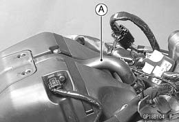
• Pull the air switching valve hose [A] out of the air cleaner base.
• Reinstall the fuel tank (see Fuel Tank Installation in the Fuel System (DFI) chapter). • Start the engine and run it at idle speed. • Plug [A] the air switching valve hose [B] end with your finger and feel vacuum pulsing in the hose.
• Apply a soap and water solution or rubber lubricant to the end of the air switching hose and install the hose on the fitting.
• Remove the air switching valve (see Air Switching Valve Removal in the Engine Top End chapter). • Set the hand tester [A] to the × Ω range and connect it to the air switching valve terminals as shown.
|
||||||||||||||||||
|
|
Последнее изменение этой страницы: 2016-08-10; просмотров: 514; Нарушение авторского права страницы; Мы поможем в написании вашей работы! infopedia.su Все материалы представленные на сайте исключительно с целью ознакомления читателями и не преследуют коммерческих целей или нарушение авторских прав. Обратная связь - 216.73.216.153 (0.008 с.) |

 Commutator Cleaning and Inspection
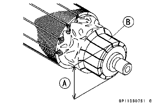 • Measure the diameter [A] of the commutator [B].
 If the commutator diameter is less than the service limit,
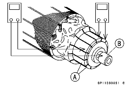 Armature Inspection
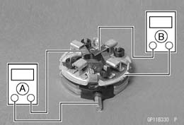 Brush Lead Inspection
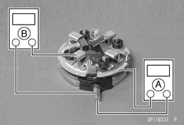 Brush Plate and Terminal Bolt Inspection
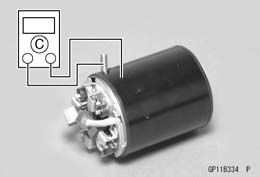 If there is any reading, the brush plate assy and/or termi- nal bolt assy have a short. Replace the brush plate assy and the terminal bolt assy.
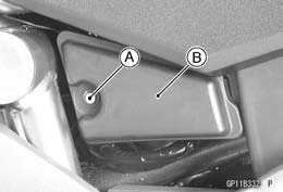 Starter Relay Inspection
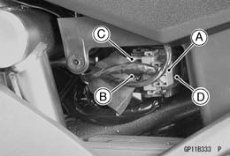 • Disconnect the connector [A].
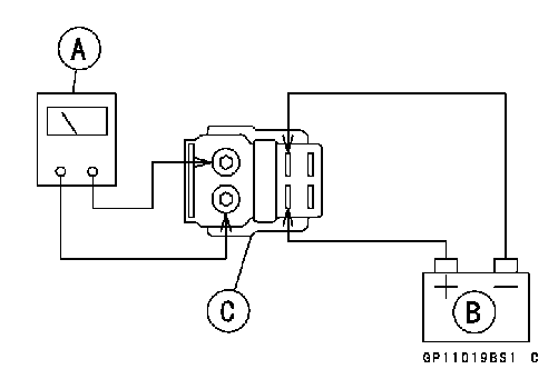 • Connect the hand tester [A] and 12 V battery [B] to the starter relay [C] as shown.
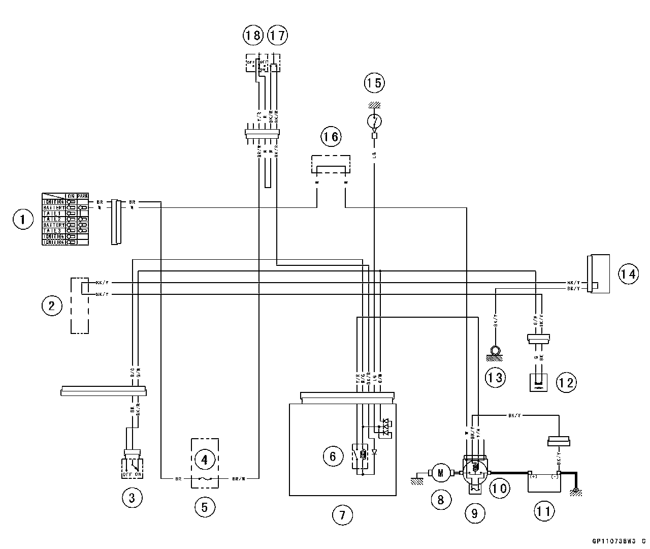
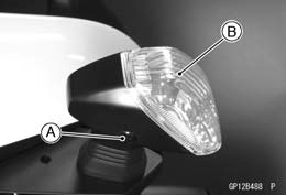
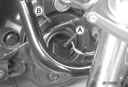 Headlight Bulb Replacement
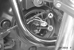 • Remove: Hook [A]
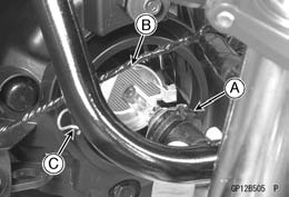 • Replace the headlight bulb.
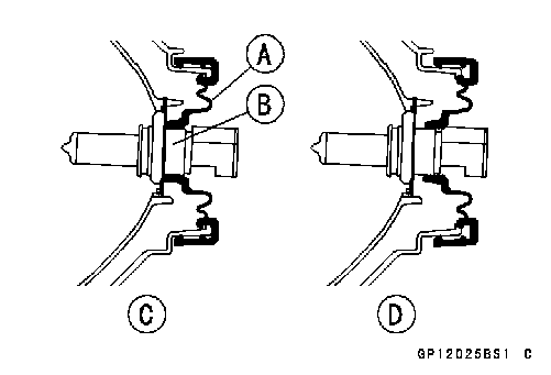 Bad [D]
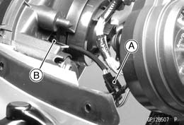 City Light Bulb Replacement (Europe Models)
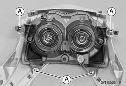 Headlight Removal/Installation
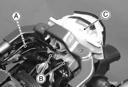 Tail/Brake Light Removal
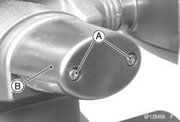 License Plate Light Bulb Replacement
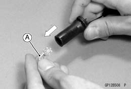
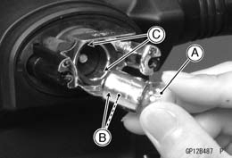 • Insert the new bulb [A] by aligning its upper and lower pins [B] with the upper and lower grooves [C] in the socket, and
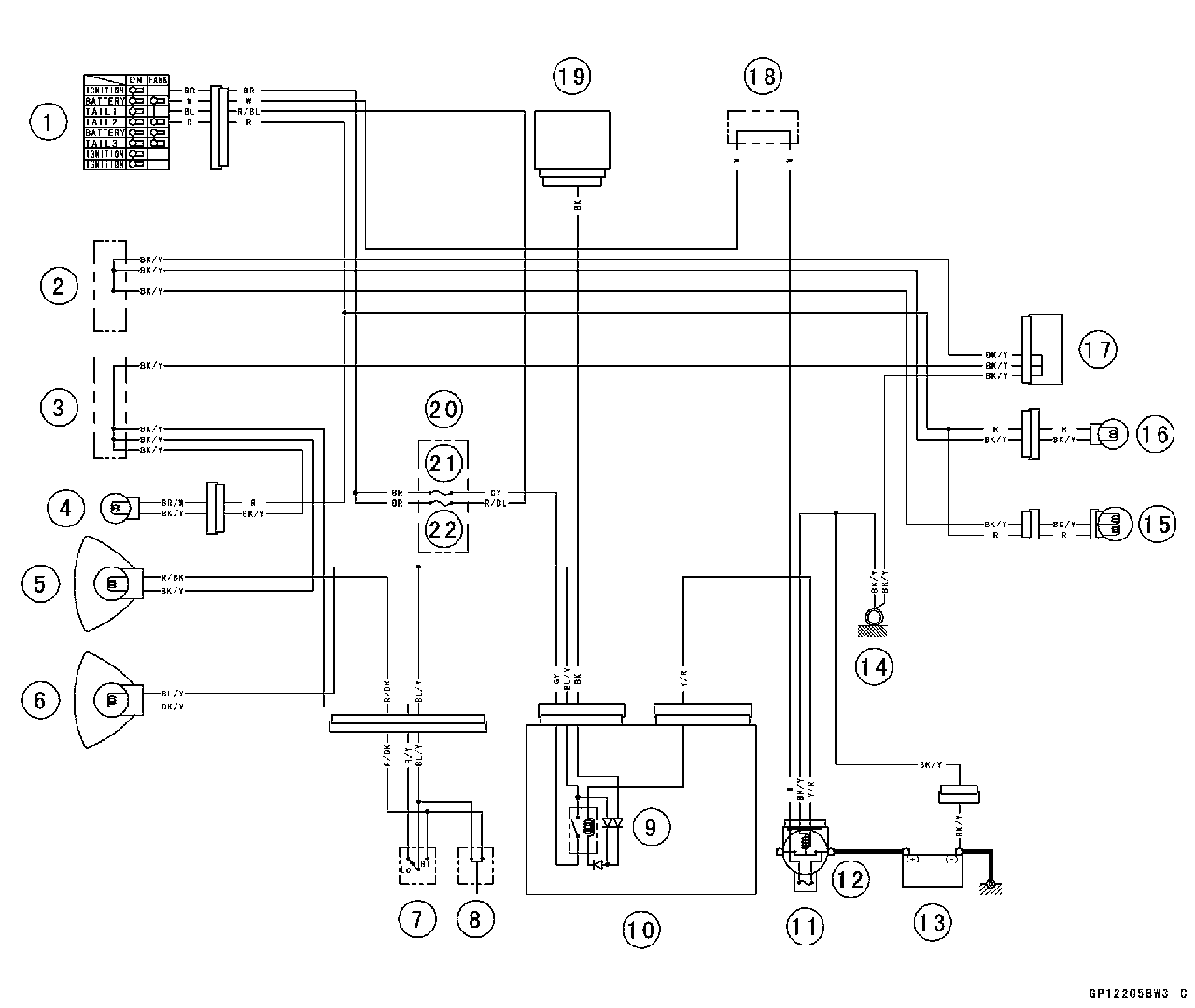
 Tail Light Fuse 10 A
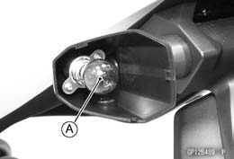 • Push and turn the bulb [A] counterclockwise and remove it.
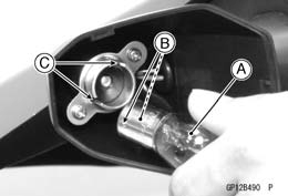 • Insert the new bulb [A] by aligning its upper and lower pins [B] with the upper and lower grooves [C] in the socket, and
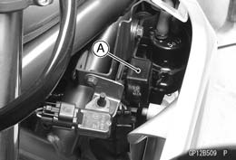 Turn Signal Relay Inspection
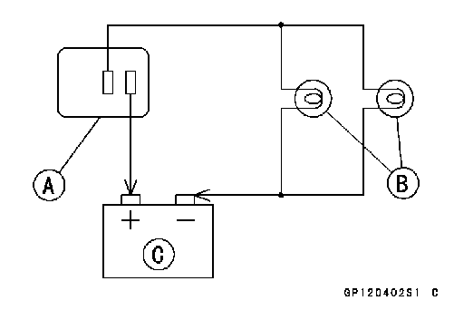 • Connect one 12 V battery and turn signal lights as indi- cated in the figure, and count how may times the lights
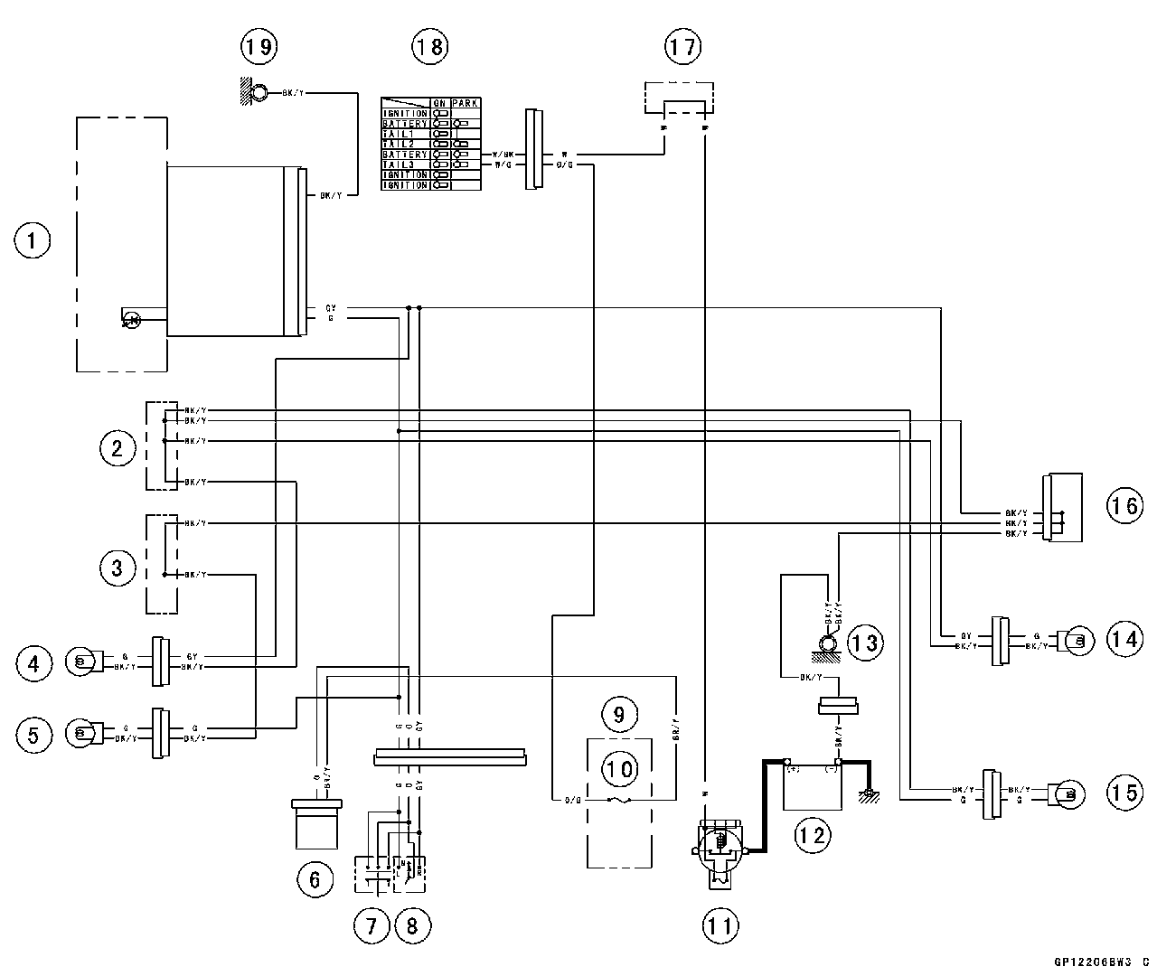
 • Remove the fuel tank (see Fuel Tank Removal in the Fuel System (DFI) chapter).
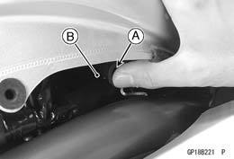 • Take the air switching valve hose end outside of the frame.
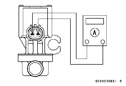 Air Switching Valve Unit Test