Заглавная страница Избранные статьи Случайная статья Познавательные статьи Новые добавления Обратная связь FAQ Написать работу КАТЕГОРИИ: ТОП 10 на сайте Приготовление дезинфицирующих растворов различной концентрацииТехника нижней прямой подачи мяча. Франко-прусская война (причины и последствия) Организация работы процедурного кабинета Смысловое и механическое запоминание, их место и роль в усвоении знаний Коммуникативные барьеры и пути их преодоления Обработка изделий медицинского назначения многократного применения Образцы текста публицистического стиля Четыре типа изменения баланса Задачи с ответами для Всероссийской олимпиады по праву 
Мы поможем в написании ваших работ! ЗНАЕТЕ ЛИ ВЫ?
Влияние общества на человека
Приготовление дезинфицирующих растворов различной концентрации Практические работы по географии для 6 класса Организация работы процедурного кабинета Изменения в неживой природе осенью Уборка процедурного кабинета Сольфеджио. Все правила по сольфеджио Балочные системы. Определение реакций опор и моментов защемления |
Recommended Disc Brake Fluid Grade: DOT4Содержание книги
Поиск на нашем сайте
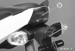
○First, tighten the rear brake fluid reservoir cap [B] clock- wise [C] by hand until slight resistance is felt indicating that the cap is seated on the reservoir body, then tighten the cap an additional 1/6 turn [D] while holding the brake fluid reservoir body [A].
limit [B], replace both pads in the caliper as a set. Pad Lining Thickness Standard: Front 4.5 mm (0.18 in.) Rear 5.0 mm (0.20 in.) Service Limit: 1 mm (0.04 in.)
• Turn on the ignition switch. • The brake light [A] should go on when the brake lever is applied or after the brake pedal is depressed about 10 mm (0.39 in.).
• Disconnect the connector [A]. • Turn the brake light switch to adjust the switch. • Connect the connector.
Brake Light (see Tail/Brake Light Removal in the Electri- cal System chapter) Main Fuse 30 A and Taillight Fuse 10 A (see Fuse In- spection in the Electrical System chapter) Front Brake Light Switch [A] (see Switch Inspection in the Electrical System chapter) Rear Brake Light Switch (see Switch Inspection in the Electrical System chapter) Harness (see Wiring Inspection in the Electrical System chapter)
Front Forks/Rear Shock Absorber Operation Inspection • Pump the forks down and up [A] 4 or 5 times, and inspect the smooth stroke.
• Visually inspect the shock absorber [A] for oil leakage.
with a new one.
Steering Play Inspection • Raise the front wheel off the ground with jack (see Front Wheel Removal in the Wheels/Tires chapter). • With the front wheel pointing straight ahead, alternately tap each end of the handlebar. The front wheel should swing fully left and right from the force of gravity until the fork hits the stop.
• Feel for steering looseness by pushing and pulling the forks.
NOTE ○The cables and wiring will have some effect on the mo- tion of the fork which must be taken into account. ○Be sure the wires and cables are properly routed. ○The bearings must be in good condition and properly lubricated in order for any test to be valid.
• Remove: Upper Inner Fairings (see Upper Inner Fairing Removal in the Frame chapter) Handlebar (see Handlebar Removal in the Steering chapter) Upper Fork Clamp Bolts [A] Steering Stem Head Bolt Plug [B] Stem Head Bolt [C] • Remove the steering stem head [D].
• Remove the steering stem locknut [B] and claw washer [C].
Special Tool - Steering Stem Nut Wrench [A]: 57001-1100
NOTE ○Turn the stem nut 1/8 turn at time maximum.
stem locknut [C]. • Hand tighten the stem locknut until it touches the claw washer. • Tighten the stem locknut clockwise until the claws are aligned with the grooves (ranging from 2nd to 4th) of stem nut [D], and bend the 2 claws downward [E]. • Install the steering stem head. • Install the washer, and tighten the stem head bolt. • Tighten: Torque - Steering Stem Head Bolt: 108 N·m (11.0 kgf·m, 80 ft·lb) Front Fork Clamp Bolts (Upper): 20 N·m (2.0 kgf·m, 15 ft·lb) • Check the steering again.
justment.
Steering Stem Bearing Lubrication • Remove the steering stem (see Stem, Stem Bearing Re- moval in the Steering chapter). • Using a high-flash point solvent, wash the upper and lower ball bearings in the cages, and wipe the upper and lower outer races, which are press-fitted into the frame head pipe, clean off grease and dirt. • Visually check the outer races and the ball bearings.
damage. • Pack the upper and lower ball bearings [A] in the cages with grease, and apply a light coat of grease to the upper and lower outer races. • Install the steering stem (see Stem, Stem Bearing Instal- lation in the Steering chapter). • Adjust the steering (see Steering Play Adjustment).
Spark Plug Condition Inspection • Remove the spark plugs (see Spark Plug Replacement). • Visually inspect the spark plugs.
trode [B] are corroded or damaged, or if the insulator [C] is cracked, replace the plug.
• Measure the gap [D] with a wire-type thickness gauge.
Spark Plug Gap: 0.8 ~ 0.9 mm (0.03 ~ 0.04 in.) • Use the standard spark plug or its equivalent. Spark Plug: CR9EIA-9
First Step • Turn on the ignition switch.
 EX650B Models EX650B Models
If the light does not go on, inspect or replace the following item.
Applicable Bulb (see Wiring Diagram in the Electrical System chapter) Meter Unit for Meter Panel LCD (see Electronic Com- bination Meter Unit Inspection in the Electrical System chapter) Meter Unit for Neutral Indicator Light (LED) (see Elec- tronic Combination Meter Unit Inspection in the Electri- cal System chapter) Meter Unit for Oil Pressure Warning Indicator Light (LED) (see Electronic Combination Meter Unit Inspec- tion in the Electrical System chapter) Meter Unit for FI Indicator Light (LED) (see Electronic Combination Meter Unit Inspection in the Electrical Sys- tem chapter) Meter Unit for Water Temperature Warning Indicator Light (LED) (see Electronic Combination Meter Unit Inspection in the Electrical System chapter) Meter Unit for ABS Indicator Light (LED) (see ABS In- dicator Light (LED) Inspection in the Brakes chapter) (EX650B Models) ECU (see ECU Power Supply Inspection in the Fuel Sys- tem (DFI) chapter) Main Fuse 30 A and Taillight Fuse 10 A (see Fuse In- spection in the Electrical System chapter) Ignition Switch (see Switch Inspection in the Electrical System chapter) Neutral Switch (see Switch Inspection in the Electrical System chapter) Harness (see Wiring Inspection in the Electrical System chapter)
• Turn off the ignition switch. • The all lights should go off.
Second Step • Turn the ignition switch to P (Park) position. • The city light, taillight and license plate light should go on.
item. Ignition Switch (see Switch Inspection in the Electrical System chapter)
• Turn on the turn signal switch [A] (left or right position). • The left or right turn signal lights [B] (front and rear) ac- cording to the switch position should flash. • The turn signal indicator light (LED) [C] in the meter unit should flash.
Turn Signal Light Bulb (see Turn Signal Light Bulb Re- placement in the Electrical System chapter)
Turn Signal Relay Fuse 10 A (see Fuse Inspection in the Electrical System chapter) Turn Signal Switch (see Switch Inspection in the Electri- cal System chapter) Turn Signal Relay (see Turn Signal Relay Inspection in the Electrical System chapter)
• Push the turn signal switch. • The turn signal lights and indicator light (LED) should go off.
Turn Signal Switch (see Switch Inspection in the Electri- cal System chapter) Turn Signal Relay (see Turn Signal Relay Inspection in the Electrical System chapter)
• Set the dimmer switch [A] to low beam position. • Start the engine. • The low beam headlight should go on.
place the following item. Headlight Low Beam Bulb (see Headlight Bulb Replace- ment in the Electrical System chapter) Headlight Fuse 10 A (see Fuse Inspection in the Electri- cal System chapter) Dimmer Switch (see Switch Inspection in the Electrical System chapter) Headlight Relay in Relay Box (see Relay Circuit Inspec- tion in the Electrical System chapter) Harness (see Wiring Inspection in the Electrical System chapter)
• The low beam [A] and high beam [B] headlights should go on. • The high beam indicator light (LED) [C] should go on.
(LED) does not go on, inspect or replace the following item. Headlight High Beam Bulb (see Headlight Bulb Replace- ment in the Electrical System chapter)
• Turn off the engine stop switch. • The low beam and high beam headlights should stay go- ing on.
Headlight Relay in Relay Box (see Relay Circuit Inspec- tion in the Electrical System chapter) • Turn off the ignition switch. • The headlights and high beam indicator light (LED) should go off. Headlight Aiming Inspection • Inspect the headlight beam for aiming.
straight ahead, adjust the horizontal beam.
• Turn the horizontal adjuster [A] on the headlight with the screwdriver in or out until the beam points straight ahead.
• Turn the vertical adjuster [A] on the headlight with the screwdriver in or out to adjust the headlight vertically.
○ON high beam, the brightest points should be slightly below horizontal with the motorcycle on its wheels and the rider seated. Adjust the headlight to the proper an- gle according to local regulations. ○For US model, the proper angle is 0.4 degrees below horizontal. This is 50 mm (2 in.) drop at 7.6 m (25 ft) measured from the center of the headlight with the motorcycle on its wheels and the rider seated.
Center of Brightest Spot [B] 7.6 m (25 ft) [C] Low Beam [D] Height of Headlight Center [E] High Beam [F]
• Inspect the sidestand switch [A] operation accordance to below table. Sidestand Switch Operation
Battery (see Charging Condition Inspection in the Elec- trical System chapter) Main Fuse 30 A (see Fuse Inspection in the Electrical System chapter) Ignition Fuse 10 A (see Fuse Inspection in the Electrical System chapter) Ignition Switch (see Switch Inspection in the Electrical System chapter) Sidestand Switch (see Switch Inspection in the Electrical System chapter) Engine Stop Switch (see Switch Inspection in the Elec- trical System chapter) Starter Button (see Switch Inspection in the Electrical System chapter) Neutral Switch (see Switch Inspection in the Electrical System chapter) Starter Relay (see Starter Relay Inspection in the Elec- trical System chapter) Relay Box (see Relay Circuit Inspection in the Electrical System chapter) Starter Circuit Relay (see Relay Circuit Inspection in the Electrical System chapter) Harness (see Wiring Inspection in the Electrical System chapter)
First Step • Turn on the ignition switch. • Set the neutral position. • Turn the engine stop switch to stop position [A]. • Push the starter button. • The engine does not start.
Engine Stop Switch (see Switch Inspection in the Elec- trical System chapter)
• Turn on the ignition switch. • Set the neutral position. • Turn the engine stop switch to run position [A]. • Push the starter button and run the engine. • Turn the engine stop switch to stop position. • Immediately the engine should be stop.
ing item. Engine Stop Switch (see Switch Inspection in the Elec- trical System chapter)
Others Chassis Parts Lubrication • Before lubricating each part, clean off any rusty spots with rust remover and wipe off any grease, oil, dirt, or grime. • Lubricate the points listed below with indicated lubricant. NOTE ○Whenever the vehicle has been operated under wet or rainy conditions, or especially after using a high-pressure water spray, perform the general lubri- cation. Pivots: Lubricate with Grease. Brake Lever Brake Pedal Clutch Lever Rear Brake Joint Pin Sidestand
Clutch Inner Cable Upper and Lower Ends [A] Throttle Inner Cable Upper and Lower Ends
Clutch Cable Throttle Cables • Lubricate the cables by seeping the oil between the cable and housing. ○The cable may be lubricated by using a commercially available pressure cable lubricator with an aerosol cable lubricant.
|
||||||||||||||||||||||||||||||||||||||||||||||||||||||||||||||||||
|
|
Последнее изменение этой страницы: 2016-08-10; просмотров: 408; Нарушение авторского права страницы; Мы поможем в написании вашей работы! infopedia.su Все материалы представленные на сайте исключительно с целью ознакомления читателями и не преследуют коммерческих целей или нарушение авторских прав. Обратная связь - 216.73.216.103 (0.006 с.) |

 • Follow the procedure below to install the rear brake fluid reservoir cap correctly.
 Brake Pad Wear Inspection
 • Check the lining thickness [A] of the pads in each caliper. If the lining thickness of either pad is less than the service
 Brake Light Switch Operation Inspection
 If it does not, adjust the brake light switch.
 If it does not go on, inspect or replace the following items. Battery (see Charging Condition Inspection in the Elec- trical System chapter)
 Suspensions
 • Pump the seat down and up [A] 4 or 5 times, and inspect the smooth stroke.
 Front Fork Oil Leak Inspection
 Rear Shock Absorber Oil Leak Inspection
 Steering System
 Steering Play Adjustment
 • Bend the claws [A] of the claw washer straighten.
 • Adjust the steering.
 • Install the claw washer [A] so that its bent side [B] faces upward, and engage the bent claws with the grooves of
 • Install the removed parts (see appropriate chapters).
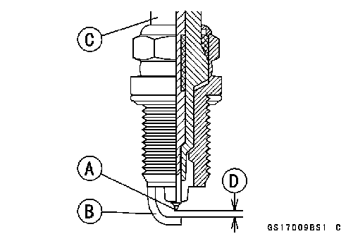 Electrical System
 Lights and Switches Operation Inspection
 Battery (see Charging Condition Inspection in the Elec- trical System chapter)
 Third Step
 If the each light does not flash, inspect or replace the following item.
 Meter Unit for Turn Signal Light Indicator Light (LED) (see Electronic Combination Meter Unit Inspection in the Electrical System chapter)
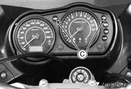 Harness (see Wiring Inspection in the Electrical System chapter)
 Fourth Step
 • Set the dimmer switch to high beam position.
 Dimmer Switch (see Switch Inspection in the Electrical System chapter)
 Headlight Beam Horizontal Adjustment
 Headlight Beam Vertical Adjustment
 NOTE
NOTE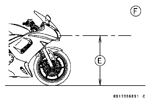 50 mm (2 in.) [A]
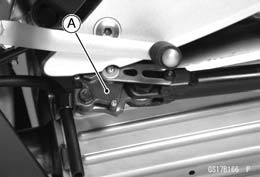 Sidestand Switch Operation Inspection
 Engine Stop Switch Operation Inspection
 Second Step
 Points: Lubricate with Grease.
 Cables: Lubricate with Rust Inhibitor.
 • With the cable disconnected at both ends, the inner cable should move freely [A] within the cable housing.