Заглавная страница Избранные статьи Случайная статья Познавательные статьи Новые добавления Обратная связь FAQ Написать работу КАТЕГОРИИ: ТОП 10 на сайте Приготовление дезинфицирующих растворов различной концентрацииТехника нижней прямой подачи мяча. Франко-прусская война (причины и последствия) Организация работы процедурного кабинета Смысловое и механическое запоминание, их место и роль в усвоении знаний Коммуникативные барьеры и пути их преодоления Обработка изделий медицинского назначения многократного применения Образцы текста публицистического стиля Четыре типа изменения баланса Задачи с ответами для Всероссийской олимпиады по праву 
Мы поможем в написании ваших работ! ЗНАЕТЕ ЛИ ВЫ?
Влияние общества на человека
Приготовление дезинфицирующих растворов различной концентрации Практические работы по географии для 6 класса Организация работы процедурного кабинета Изменения в неживой природе осенью Уборка процедурного кабинета Сольфеджио. Все правила по сольфеджио Балочные системы. Определение реакций опор и моментов защемления |
Sealant - Kawasaki Bond: 92104-1064Содержание книги
Поиск на нашем сайте NOTE ○Especially, apply a liquid gasket carefully so that it shall be filled up on the grooves.
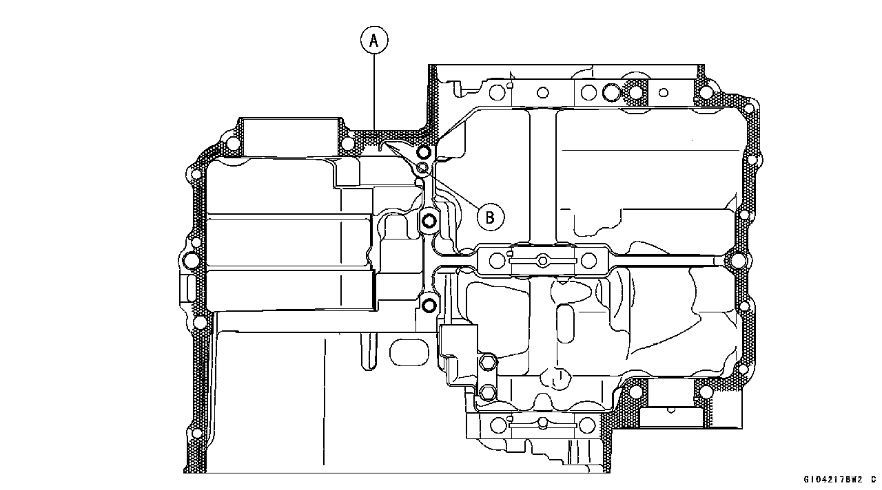
○Do not apply liquid gasket to the oil passage [B].
○Insert [A] the breather pipe [B] on the upper crankcase half through the hole [C] on the lower crankcase half. NOTE ○Make the application finish within 20 minutes when the liquid gasket to the mating surface of the lower crankcase half is applied. ○Moreover fit the case and tighten the case bolts just after finishing the application of the liquid gasket.
• Apply molybdenum disulfide oil solution to both sides [A] of the M9 bolts washers and the threads [B] of the M9 bolts.
[7 ~ 10] only (see the next figure).
○Following the sequence numbers on the lower crankcase half, tighten the M9 bolts [1, 2] L= 113 mm (4.45 in.) with washers. Torque - Crankcase Bolts (M9): 44 N·m (4.5 kgf·m, 32 ft·lb) ○Tightenthe M9 bolts [3, 4] L= 83 mm (3.27 in.) with wash- ers. Torque - Crankcase Bolts (M9): 44 N·m (4.5 kgf·m, 32 ft·lb) ○Tighten the M9 bolts [5, 6] L= 113 mm (4.45 in.) with washers. Torque - Crankcase Bolts (M9): 44 N·m (4.5 kgf·m, 32 ft·lb) ○Tighten the M8 bolts [7 ~10]. Torque - Crankcase Bolts (M8): 35 N·m (3.6 kgf·m, 26 ft·lb) ○Tighten the M8 bolts [A] (Do not apply molybdenum oil solution). Torque - Crankcase Bolts (M8): 27.5 N·m (2.8 kgf·m, 20 ft·lb) ○Tighten the M6 bolts [B]. Torque - Crankcase Bolts (M6): 19.6 N·m (2.0 kgf·m, 15 ft·lb)
○The upper crankcase bolts have copper plated washers. Replace them with new ones. Torque - Upper Crankcase Bolts [A]: 27.5 N·m (2.8 kgf·m, 20 ft·lb) • After tightening all crankcase bolts, check the following items. ○Crankshaft and balancer shafts turn freely.
Crankshaft Removal
• Remove the crankshaft [A].
 Crankshaft Installation Crankshaft Installation
• Apply molybdenum disulfide oil solution to the crankshaft main bearing inserts. ○Align [A] the timing mark on the balancer gear [B] with the timing mark on the balancer drive gear [C] of the crank- shaft.
• Split the crankcase (see Crankcase Splitting). • Remove the connecting rod nuts [A]. • Remove the crankshaft. NOTE ○Mark and record the locations of the connecting rods and their big end caps so that they can be reassembled in their original positions.
Connecting Rod Installation
Big End Cap [A] Connecting Rod [B] Weight Mark, Alphabet [C] Diameter Mark [D]: “○” or no mark
necting rod big end. • Apply molybdenum disulfide oil solution [B] to the inner surfaces of upper and lower bearing inserts. ○The molybdenum disulfide oil solution is a mixture of en- gine oil and molybdenum disulfide grease with a weight ratio (10: 1). ○Do not apply any grease or oil [C] to the cap inside and cap insert outside. ○Install the inserts so that their nails [D] are on the same side and fit them into the recess of the connecting rod and
cap. ○When installing the inserts [A], be careful not to damage the insert surface with the edge of the connecting rod [B] or the cap [C]. One way to install inserts is as follows.
Installation [E] to Connecting Rod Push [F] Spare Dowel Pin [G] Connecting Rod Bolts [H] • Install the cap on the connecting rod, aligning the weight and diameter marks. • Remove debris and clean the surface of inserts. • Apply molybdenum disulfide oil solution [MO] to the threads and seating surfaces of the big end nuts and bolts.
• Install each connecting rod on its original crankpin. NOTE ○Install each connecting rod so that its oil jet [A] faces the exhaust side (the front [B]) (see Engine Oil Flow Chart in the Engine Lubrication System chapter). ○The connecting rod big end is bolted using the “plastic region fastening method”. ○This method precisely achieves the needed clamping force without exceeding it unnecessarily, allowing the use of thinner, lighter bolts further decreasing connecting rod weight. ○There are two types of the plastic region fastening. One is a bolt length measurement method and other is a rotation
angle method. Observe one of the following two, but the bolt length measurement method is preferable because this is a more reliable way to tighten the big end nuts.
(1) Bolt Length Measurement Method • Be sure to clean the bolts, nuts, and connecting rods thoroughly with a high-flash point solvent, because the new connecting rods, bolts, and nuts are treated with an anti-rust solution.
• Dent both bolt head and bolt tip with a punch as shown. • Before tightening, use a point micrometer [A] to measure the length of new connecting rod bolts and record the val- ues to find the bolt stretch. Connecting Rod [B] Mark here with a punch [C]. Nuts [D] Fit micrometer pins into punch marks [E]. • Apply a small amount of molybdenum disulfide oil solution to the following. Threads of Nuts and Bolts Seating Surfaces of Nuts and Con-rods • Tighten the big end nuts until the bolt elongation reaches the length specified in the table. • Check the length [F] of the connecting rod bolts.
stretched too much. An overelongated bolt may break in use. Bolt Length after tightening – Bolt Length before tightening = Bolt Stretch
(2) Rotation Angle Method
• Be sure to clean the bolts and nuts thoroughly with a high -flash point solvent, because the new bolts and nuts are treated with an anti-rust solution.
• Apply a small amount of molybdenum disulfide oil solution to the following. Threads [A] of Nuts and Bolts Seating Surfaces [B] of Nuts and Con-rods
• Next, tighten the nuts 120° ±5°. ○Mark [A] the connecting rod big end caps and nuts so that nuts can be turned 120° [B] properly.
Crankshaft/Connecting Rod Cleaning • After removing the connecting rods from the crankshaft, clean them with a high-flash point solvent. • Blow the crankshaft oil passages with compressed air to remove any foreign particles or residue that may have accumulated in the passages.
• Remove the connecting rod big end bearing inserts, and reinstall the connecting rod big end cap. • Select an arbor [A] of the same diameter as the connect- ing rod big end, and insert the arbor through the connect- ing rod big end. • Select an arbor of the same diameter as the piston pin and at least 100 mm (3.94 in.) long, and insert the arbor [B] through the connecting rod small end. • On a surface plate, set the big-end arbor on V block [C]. • With the connecting rod held vertically, use a height gauge to measure the difference in the height of the
Connecting Rod Bend
|
||||||||||||||||||||||||||||||||||||||||||||||||||||||||
|
|
Последнее изменение этой страницы: 2016-08-10; просмотров: 645; Нарушение авторского права страницы; Мы поможем в написании вашей работы! infopedia.su Все материалы представленные на сайте исключительно с целью ознакомления читателями и не преследуют коммерческих целей или нарушение авторских прав. Обратная связь - 216.73.216.150 (0.006 с.) |

 • Fit the lower crankcase half to the upper crankcase half.
 ○The M9 bolts [1 ~6] (see the next figure) have copper plated washers. Replace them with new ones.
 • Apply molybdenum disulfide oil solution to flange [A] and the threads [B] of the M8 bolts which is tightening order is
 • Tighten the lower crankcase bolts using the following steps.
 • Tighten the upper crankcase bolts.
 • Split the crankcase (see Crankcase Splitting).
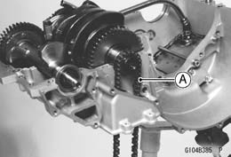 • Install the crankshaft with the camshaft chain [A] hanging on it.
 Connecting Rod Removal
 • Apply molybdenum disulfide grease [A] to the outer sur- face of the upper insert and the inner surface of the con-
 Installation [D] to Cap
 • Install the crankshaft (see Crankshaft Installation).
 • Install new bolts in reused connecting rods.
 If the stretch is more than the usable range, the bolt has
 • Install new bolts in reused connecting rods.
 • First, tighten the nuts to the specified torque. See the table below.
 Connecting Rod Bend