
Заглавная страница Избранные статьи Случайная статья Познавательные статьи Новые добавления Обратная связь FAQ Написать работу КАТЕГОРИИ: ТОП 10 на сайте Приготовление дезинфицирующих растворов различной концентрацииТехника нижней прямой подачи мяча. Франко-прусская война (причины и последствия) Организация работы процедурного кабинета Смысловое и механическое запоминание, их место и роль в усвоении знаний Коммуникативные барьеры и пути их преодоления Обработка изделий медицинского назначения многократного применения Образцы текста публицистического стиля Четыре типа изменения баланса Задачи с ответами для Всероссийской олимпиады по праву 
Мы поможем в написании ваших работ! ЗНАЕТЕ ЛИ ВЫ?
Влияние общества на человека
Приготовление дезинфицирующих растворов различной концентрации Практические работы по географии для 6 класса Организация работы процедурного кабинета Изменения в неживой природе осенью Уборка процедурного кабинета Сольфеджио. Все правила по сольфеджио Балочные системы. Определение реакций опор и моментов защемления |
Stick Coil Primary Peak Voltage Standard: 88 V or moreСодержание книги
Поиск на нашем сайте • Repeat the test for the other stick coil.
following. Stick Coils (see Stick Coil (Ignition Coil together with Spark Plug Cap) Inspection) Crankshaft Sensor (see Crankshaft Sensor Inspection) ECU (see ECU Power Supply Inspection in the Fuel Sys- tem (DFI) chapter) Spark Plug Removal • Refer to the Spark Plug Replacement in the Periodic Maintenance chapter. Spark Plug Installation • Refer to the Spark Plug Replacement in the Periodic Maintenance chapter. Spark Plug Condition Inspection • Refer to the Spark Plug Condition Inspection in the Peri- odic Maintenance chapter. Interlock Operation Inspection • Raise the rear wheel off the ground with stand. 1st Check • Start the engine to the following conditions. Condition Transmission Gear → 1st Position Clutch Lever → Release Sidestand → Down or Up ○Turn the ignition switch ON and push the starter button. ○Then the starter motor should not turn when the starter system circuit is normality.
2nd Check • Start the engine to the following conditions. Condition Transmission Gear → 1st Position Clutch Lever → Pulled in Sidestand → Up ○Turn the ignition switch ON and push the starter button. ○Then the starter motor should turn when the starter sys- tem circuit is normality.
3rd Check • Inspect the engine for its secure stop after the following operations are completed. • Run the engine to the following conditions. Condition Transmission Gear → 1st Position Clutch Lever → Pulled in Sidestand → Up • Set the sidestand on the ground, then the engine will stop.
switch, starter lockout switch, sidestand switch and relay box.
○The IC igniter is built in the ECU [A]. • Refer to the Interlock Operation Inspection, Ignition Sys- tem Troubleshooting chart and Fuel System (DFI) chapter for ECU Power Supply Inspection.
1. Ignition Switch 2. Engine Stop Switch 3. Spark Plugs 4. Stick Coils 5. Water-proof Joint C 6. Speed Sensor 7. Subthrottle Sensor 8. Main Throttle Sensor 9. Water-proof Joint D 10. Vehicle-down Sensor 11. Water-proof Joint E 12. Water Temperature Sensor 13. Neutral Switch 14. Crankshaft Sensor 15. Oxygen Sensor 16. Meter Unit 17. Water-proof Joint A 18. Water-proof Joint B 19. Starter Lockout Switch 20. Oxygen Sensor Heater Fuse 10 A 21. ECU Fuse 15 A 22. Ignition Fuse 10 A 23. Fuse Box 24. ECU Main Relay 25. Relay Box 26. Main Fuse 30 A 27. Starter Relay 28. Battery 12 V 10 Ah 29. Frame Ground 30. Sidestand Switch 31. Joint Connector 32. ECU
Starter Motor Removal
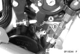
• Remove: Fuel Tank (see Fuel Tank Removal in the Fuel System (DFI) chapter) Right Center Fairing (see Center Fairing Removal in the Frame chapter) • Slide back the rubber cap [A]. • Remove the starter motor cable terminal nut [B].
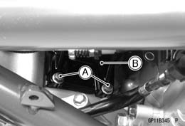
• Pull out the starter motor [B].
 Starter Motor Installation Starter Motor Installation
• When installing the starter motor, clean the starter mo- tor legs [A] and crankcase [B] where the starter motor is grounded.
• Apply grease to the O-ring. • Apply a non-permanent locking agent to the threads of the bolts and tighten the bolts. Torque - Starter Motor Mounting Bolts: 9.8 N·m (1.0 kgf·m, 87 in·lb) • Install the starter motor cable. • Tighten: Torque - Starter Motor Cable Terminal Nut: 6.0 N·m (0.60 kgf·m, 53 in·lb)
Starter Motor Disassembly
• Take off the starter motor through bolts [A] and remove the both end covers [B] and pull the armature out of the yoke [C].
Terminal Locknut and Washers O-ring • Remove the brush plate assy [A] from the yoke [B].
NOTE ○Do not remove the negative carbon brushes form the brush plate.
• Install the brush plate [A] to the plate cover [B] as shown. • Install the brush plate assy to the yoke.
• Fit the armature [C] to the brush plate assy [D]. • Remove the clips.
• Install: Washers [B] and Terminal Locknut [C] • Tighten: Torque - Starter Motor Terminal Locknut: 11 N·m (1.1 kgf·m, 97 in·lb)
• Tighten the through bolts. Torque - Starter Motor Through Bolts: 4.9 N·m (0.50 kgf·m, 43 in·lb)
• Measure the length of each brush [A].
plate assy [B] and the terminal bolt assy [C].
|
||||||
|
|
Последнее изменение этой страницы: 2016-08-10; просмотров: 417; Нарушение авторского права страницы; Мы поможем в написании вашей работы! infopedia.su Все материалы представленные на сайте исключительно с целью ознакомления читателями и не преследуют коммерческих целей или нарушение авторских прав. Обратная связь - 216.73.216.153 (0.008 с.) |

 If the reading is less than the specified value, check the
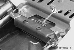 IC Igniter Inspection

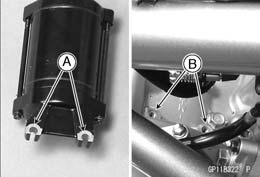
 • Remove the mounting bolts [A].
 • Replace the O-ring [A] with a new one.
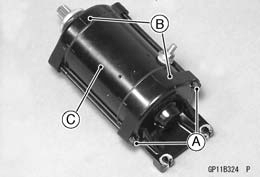 • Remove the starter motor (see Starter Motor Removal).
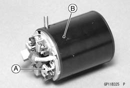 • Remove:
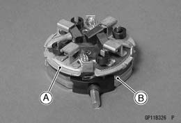 • Remove the brush plate [A] from the plate cover [B].
 • Clamp the springs [A] with the clips [B].
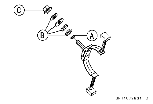 • Install the new O-ring [A] as shown.
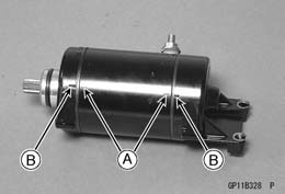 • Align the lines [A] on the yoke with the end cover lines [B].
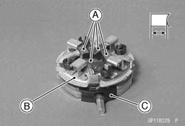 Brush Inspection