Заглавная страница Избранные статьи Случайная статья Познавательные статьи Новые добавления Обратная связь FAQ Написать работу КАТЕГОРИИ: ТОП 10 на сайте Приготовление дезинфицирующих растворов различной концентрацииТехника нижней прямой подачи мяча. Франко-прусская война (причины и последствия) Организация работы процедурного кабинета Смысловое и механическое запоминание, их место и роль в усвоении знаний Коммуникативные барьеры и пути их преодоления Обработка изделий медицинского назначения многократного применения Образцы текста публицистического стиля Четыре типа изменения баланса Задачи с ответами для Всероссийской олимпиады по праву 
Мы поможем в написании ваших работ! ЗНАЕТЕ ЛИ ВЫ?
Влияние общества на человека
Приготовление дезинфицирующих растворов различной концентрации Практические работы по географии для 6 класса Организация работы процедурного кабинета Изменения в неживой природе осенью Уборка процедурного кабинета Сольфеджио. Все правила по сольфеджио Балочные системы. Определение реакций опор и моментов защемления |
Ignition coil primary peak voltageСодержание книги
Поиск на нашем сайте
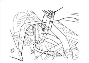
Shift the transmission into neutral and disconnect the spark plug cap (page 3-5).
Connect a known good spark plug [1] to the spark plug cap [2] and ground it to the cylinder head as done in a spark test.
[1]
[2]
Avoid touching the spark plug and tester probes to prevent electric shock.
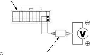
With the ignition coil primary wire connected, connect
TOOL:
Imrie diagnostic tester (model 625) or
with commercially available digital multimeter (impedance 10 MΩ/DCV minimum)
CONNECTION: Green/red (+) – Ground (–)
Shift the transmission into neutral.
Turn the ignition switch ON and engine stop switch "
Crank the engine with the starter motor with the throttle grip fully opened and read ignition coil primary peak voltage.
PEAK VOLTAGE: 100 V minimum
If the peak voltage is abnormal, follow the checks described in the troubleshooting table (page 5-2).
5-4 IGNITION SYSTEM
CKP SENSOR PEAK VOLTAGE
Remove the reserve tank cover (page 2-4).
[1]
Disconnect the ECM 33P (Black) connector [1].
5-5 IGNITION SYSTEM
IGNITION TIMING
Connect the timing light [1] to the spark plug wire.
Start the engine and let it idle.
IDLE SPEED: 1,450 ± 100 min-1 (rpm)
Apply engine oil to a new O-ring and install it to the timing hole cap.
Apply engine oil to the timing hole cap threads.
Install and tighten the timing hole cap to the specified torque.
TORQUE:6.0 N·m (0.6 kgf·m, 4.4 lbf·ft)
IGNITION COIL
REMOVAL/INSTALLATION
Disconnect the spark plug cap [1].
Disconnect the primary wire connectors [2] from the ignition coil.
Release the spark plug wire [3] from the guides [4] on the fan motor shroud.
Remove the bolts [5], spacers [6] and ignition coil [7]. Installation is in the reverse order of removal.
[5]/[6] [2]
[4]
[3] [1]
5-6 ELECTRIC STARTER SYSTEM
SERVICE INFORMATION·····························6-2 STARTER MOTOR ·······································6-4
TROUBLESHOOTING···································6-2 STARTER RELAY SWITCH ·························6-8
SYSTEM LOCATION·····································6-3 NEUTRAL DIODE ·········································6-9
SYSTEM DIAGRAM ······································6-3
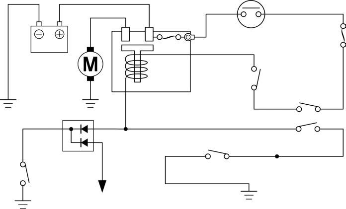
6-1 ELECTRIC STARTER SYSTEM
SERVICE INFORMATION
GENERAL
• When servicing the starter system, always follow the steps in the troubleshooting flow chart (page 6-2). • A weak battery may be unable to turn the starter motor quickly enough, or supply adequate ignition current.
TROUBLESHOOTING
6-2
SYSTEM LOCATION
ENGINE STOP SWITCH ELECTRIC STARTER SYSTEM
STARTER SWITCH
MAIN FUSE (30 A)
FI. IGN FUSE (10 A)
STARTER MOTOR
NEUTRAL SWITCH
SYSTEM DIAGRAM
|
||||||||||||||||||||||||||||||||||||||||||||||||||||||||||||||||||||||||||||||||||||||||||||||||||||||||||||||||||||||||||||||||||||||||||||||||||||||||||||||||||||||||||||||||||||||||||||||||||||||||||||||||||||||||||||||||||||||||||||||||||||||||||||||||||||||||||||||||||||||||||||||||||||||||||||||||||||||||||||||||||||||||||||||||||||||||||||||||||||||||||||||||||||||||||||||||||||||||||||||||||||||||||||||||||||||||||||||||||||||||||||||||||||||||||||||||||||||||||||||||||||||||||||||||||||||||||||||||||||||||||||||||||||||||||||||||||||||||||||||||||||||||||||||||||||||||||||||||||||||||||||||||||||||||||||||||||||||||||||||||||||||||||||||||||||||||||||||||||||||||||||||||||||||||||||||||||||||||||||||||||||||||||||||||||||||||||||||||||||||||||||||||||||||||||||||||||||||||||||||||||||||||||||||||||||||||||||||||||||||||||||||||||||||||||||||||||||||||||||||||||||||||||||||||||||||||||||||||||||||||||||||||||||||||||||||||||||||||||||||||||||||||||||||||||||||||||||||||||||||
|
|
Последнее изменение этой страницы: 2016-04-08; просмотров: 725; Нарушение авторского права страницы; Мы поможем в написании вашей работы! infopedia.su Все материалы представленные на сайте исключительно с целью ознакомления читателями и не преследуют коммерческих целей или нарушение авторских прав. Обратная связь - 216.73.217.86 (0.009 с.) |


 the peak voltage adaptor or Imrie tester to the ignition [1] coil primary terminal [1] and ground.
 ".
".


 CKP sensor connector.


 [7]
[7]