Заглавная страница Избранные статьи Случайная статья Познавательные статьи Новые добавления Обратная связь FAQ Написать работу КАТЕГОРИИ: ТОП 10 на сайте Приготовление дезинфицирующих растворов различной концентрацииТехника нижней прямой подачи мяча. Франко-прусская война (причины и последствия) Организация работы процедурного кабинета Смысловое и механическое запоминание, их место и роль в усвоении знаний Коммуникативные барьеры и пути их преодоления Обработка изделий медицинского назначения многократного применения Образцы текста публицистического стиля Четыре типа изменения баланса Задачи с ответами для Всероссийской олимпиады по праву 
Мы поможем в написании ваших работ! ЗНАЕТЕ ЛИ ВЫ?
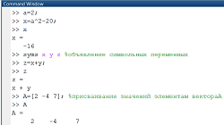
Влияние общества на человека
Приготовление дезинфицирующих растворов различной концентрации Практические работы по географии для 6 класса Организация работы процедурного кабинета Изменения в неживой природе осенью Уборка процедурного кабинета Сольфеджио. Все правила по сольфеджио Балочные системы. Определение реакций опор и моментов защемления |
Disassembly/assembly (left side only)Содержание книги
Поиск на нашем сайте
Remove the screws [1] and separate the side lower cover [2] from the left side cover [3] by releasing its slots [4] and holes [5] from the hooks and bosses of the side cover.
Assembly is in the reverse order of disassembly.
TORQUE:
Left side cover assembly screw: 0.9 N·m (0.1 kgf·m, 0.7 lbf·ft)
Align
[3]
[4]
[1] [2] (Right side only)
[1]
[5]
2-3 FRAME/BODY PANELS/EXHAUST SYSTEM
RESERVE TANK COVER
REMOVAL/INSTALLATION
Remove the trim clips [1], socket bolt [2] and reserve tank cover [3].
Installation is in the reverse order of removal.
• Align the cover boss [4] with the hole [5] of the stay.
[3]
[1]
[5]
[2]
FUEL TANK SHROUD
REMOVAL/INSTALLATION
Right side only: Remove the reserve tank cover (page 2-4).Remove the side cover (page 2-3).
Remove the socket bolt A [1], socket bolts B [2] and fuel tank shroud [3].
Installation is in the reverse order of removal.
DISASSEMBLY/ASSEMBLY
Right side: Remove the four screws [1] and separate the grille [2]and front shroud [3] from the rear shroud [4] by releasing its tabs [5] and boss [6] from the slots and hole of the rear shroud.
Left side: Remove the two screws [1] and separate the frontshroud [3] from the rear shroud [4] by releasing its tabs [5] and boss [6] from the slots and hole of the rear shroud.
Assembly is in the reverse order of disassembly.
TORQUE:
Fuel tank shroud assembly screw: 0.9 N·m (0.1 kgf·m, 0.7 lbf·ft)
[1]
[3]
2-4 FRAME/BODY PANELS/EXHAUST SYSTEM
SKID PLATE
REMOVAL/INSTALLATION
Remove the two bolts [1] and skid plate [2]. Installation is in the reverse order of removal.
• Align the rear side of the skid plate with the frame slot [3].
HEADLIGHT COWL
REMOVAL/INSTALLATION
[3]
[1]
[2]
Remove the four bolt/washers [1] and headlight cowl [2].
Disconnect the headlight 3P (Black) connector [3] and position light 2P (Black) connector [4].
Installation is in the reverse order of removal.
TORQUE:
Headlight cowl mounting bolt: 8.5 N·m (0.9 kgf·m, 6.3 lbf·ft)
[2]
[3]
[4]
FRONT FENDER
REMOVAL/INSTALLATION
Remove the four bolt/washers [1], front fender [2] and collars [3]
Installation is in the reverse order of removal.
[1]
[3]
[2]
[1]
2-5 FRAME/BODY PANELS/EXHAUST SYSTEM
FRAME GUARD
REMOVAL/INSTALLATION
Remove the socket bolts [1] and frame guard [2].
Installation is in the reverse order of removal.
[1]
DRIVE SPROCKET COVER
REMOVAL/INSTALLATION
Remove the bolts [1] and drive sprocket cover [2].
Installation is in the reverse order of removal.
[2]
DRIVE CHAIN COVER (U TYPE ONLY)
REMOVAL/INSTALLATION
Remove the socket bolts [1] and drive chain cover [2]. Installation is in the reverse order of removal.
[2]
[1]
2-6 FRAME/BODY PANELS/EXHAUST SYSTEM
TOOL BOX
REMOVAL/INSTALLATION
Remove the following:
– Seat (page 2-3)
– Left side cover (page 2-3)
Remove the two mounting bolts [1] and tool box [2]. Installation is in the reverse order of removal.
DISASSEMBLY/ASSEMBLY
Disassemble and assemble the tool box as following illustration.
HINGE
TOOL BOX
TOOL BOX COVER
SPECIAL
LOCK SPRING
LOCK UNIT
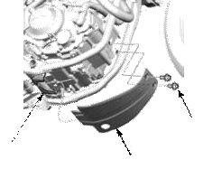
REAR FENDER
REMOVAL/INSTALLATION
Remove the bolts [1] and rear fender [2].
[1]
2-7 FRAME/BODY PANELS/EXHAUST SYSTEM
DISASSEMBLY/ASSEMBLY (U TYPE ONLY)
Remove the nuts [1], bolts [2], collars [3], license holder plate [4] and license plate stay [5].
Remove the stopper rubber [6].
Remove the nuts [7] and rear side reflectors [8]. Assembly is in the reverse order of disassembly.
TORQUE:
Rear side reflector mounting nut: 1.5 N·m (0.2 kgf·m, 1.1 lbf·ft)
[2] [5]
[4]
[8]
REAR UPPER FENDER
REMOVAL/INSTALLATION
[4] [3]
TAIL COVER/LIGHT UNIT
Remove the bolts A [2], bolts B [3] and tail cover/light unit [4].
Installation is in the reverse order of removal.
[4]
2-8 FRAME/BODY PANELS/EXHAUST SYSTEM
DISASSEMBLY/ASSEMBLY
Remove the following:
– Rear fender (page 2-7) – Rear turn signal units (page 20-4)
Disassemble and assemble the tail cover/light unit as following illustration.
REFLECTOR
MOUNTING NUT
RIGHT TAIL COVER
REAR REFLECTOR
BRAKE/TAILLIGHT UNIT
LEFT TAIL COVER
SCREW
BRAKE/TAILLIGHT MOUNTING SCREWS
4.5 N·m (0.5 kgf·m,
3.3 lbf·ft)
COLLARS
REAR TURN SIGNAL UNIT STAY
REAR LOWER FENDER
REMOVAL/INSTALLATION
Remove the following:
– Seat (page 2-3) [1] – Side covers (page 2-3) – Tail cover/light unit (page 2-8)
Release the wire bands [1].
2-9
|
|||||||||||||||||||||||||||||||||||||||||||||||||||||||||||||||||||||||||||||||||||||||||||||||||||||||||||||||||||||||||||||||||||||||||||||||||||||||||||||||||||||||||||||||||||||||||||||||||||||||||||||||||||||||||||||||||||||||||||||||||||||||||||||||||||||||||||||||||||||||||||||||||||||||||||||||||||||||||||||||||||||||||||||||||||||||||||||||||||||||||||||||||||||||||||||||||||||||||||||||||||||||||||||||||||||||||||||||||||||||||||||||||||||||||||||||||||||||||||||||||||||||||||||
|
|
Последнее изменение этой страницы: 2016-04-08; просмотров: 429; Нарушение авторского права страницы; Мы поможем в написании вашей работы! infopedia.su Все материалы представленные на сайте исключительно с целью ознакомления читателями и не преследуют коммерческих целей или нарушение авторских прав. Обратная связь - 216.73.217.86 (0.008 с.) |


 [4]
[4]


 [2]
[2] [1]
[1]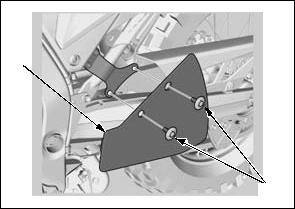


 WASHER